3DHOP
3D Heritage Online PresenterHow To
Description
This page shows you how to create a complex scene with 3DHOP, describing how to apply transformations to objects and how to manage the whole scene.
Featured Scene Elements
- Meshes
- ModelInstances
- Space
Complex scene definition
Click to run live demo
Multi-object 3D scenes with 3DHOP
Set Up
In the previous examples, we have used a single 3D model (already correctly oriented with respect to the world axis), or two 3D models (already correctly oriented with respect to the world axis AND correctly positioned one with respect to the other).
If your 3D model is not "straight" with respect to the world axis, and you need to control its orientation, or if you have more than one 3D model to arrange in the scene with a specific position/orientation/scale, you will have to use transformations.
In 3DHOP, it is possible to assign a transformation to both meshes and instances, providing the user a way to finely control the disposition of object in the scene.
A "transform" element is used to specify a combination of rotation, translation and scaling, or even a non-rigid transformation. Depending on where the "transform" element is used, you may obtain different effects. When a transformation is specified for one of the instances in the "modelInstances" section, the transformation will be applied only to that specific instance. On the other hand, when a transformation is specified for one of the meshes in the "meshes" section, it will be applied every time the mesh will be used (in ALL the instances and spots that use it). Finally, it is also possible to specify a transformation in the "scene" section, and that transformation will be applied for every element of the scene (ALL spots and instances). Transformations will stack: if an instance has a transformation, and also its mesh has a transformation, both will be used, concatenated; the same will apply to the scene transformation. Transformation stacking always follows the same order, first it is applied the scene transform, then the mesh transform and finally the instance/spot transform. This three-level transformation system is flexible enough for most of the situations.
This source code taken from the 3DHOP example of this tutorial, shows a mesh transformation applied at the "meshes" level: in this case we load a simple cube, and scale it to transform it into a "table" where we will arrange the other models.
This is the ideal place to specify those transformations that are used to make the 3D models "suitable" for your scene. For example, when a model is "not straight" with respect to the axis, and by using a rotation transformation we can put it "straight"; or when a model is not in the same scale of the rest of the scene, and by using a scaling transformation we can restore its correct size.
var presenter = null;

function setup3dhop() {
  presenter = new Presenter("draw-canvas");

  presenter.setScene({
    meshes: {
      "Laurana": {
        url: "models/laurana.ply"
      },
      "Gargoyle": {
        url: "models/gargo.nxs"
      },
      "Box": {
        url: "models/cube.ply",
        transform: { matrix: SglMat4.scaling([13.0, 0.5, 10.0]) },
      }
    },
    ...
Conversely, when we want to change the orientation/position/scale of a single instance, you need to specify a transformation when declaring the instance in the "modelInstances" section.
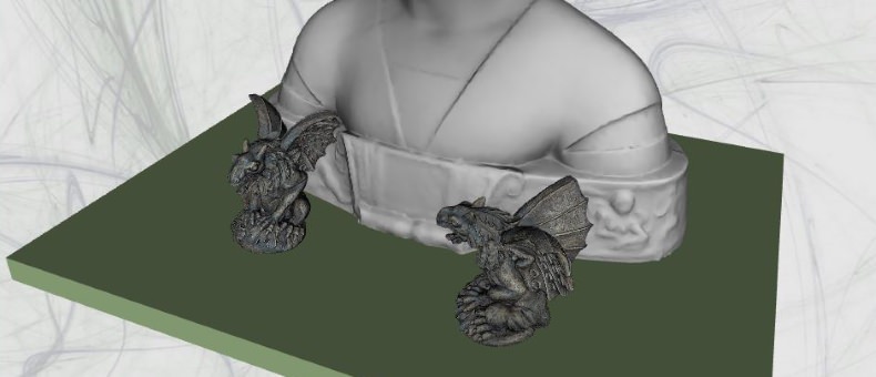
In the following block of code we can see how different instances are arranged in the scene.
- The "Base" instance uses the "Box" mesh and no transformation is specified for the instance, but since the "Box" mesh has a transformation (the scaling to change the cube into a table), this mesh transformation will still be applied
- The "Center" instance, that uses the "Laurana" mesh without transformation, is placed on top of the box using a transformation specified with a complete 4x4 matrix.
- The "Left" and "Right" instances both use the "Gargoyle" mesh, that has no transformation. In the "Right" case, a double transformation is applied, by concatenating two transformations: the model is firstly rotated (-90 degrees on the vertical axis) and then translated (on top of the box, slightly on the right). In the "Left" case, the transformation uses a translation, a rotation and a scaling (that puts the gargoyle on top of the box, slightly on the left, rotated towards the other one, and larger).
... modelInstances: { "Base" : { mesh : "Box" }, "Center" : { mesh : "Laurana", transform : { matrix: [1.0, 0.0, 0.0, 0.0, 0.0, 1.0, 0.0, 0.0, 0.0, 0.0, 1.0, 0.0, 0.0, 250.0, -50.0, 1.0] }, }, "Left" : { mesh : "Gargoyle", transform : {translation: [-120.0, 12.5, 150.0], rotation : [0.0, 90, 0.0],scale: [1.5, 1.5, 1.5] } }, "Right" : { mesh : "Gargoyle", transform : { matrix: SglMat4.mul(SglMat4.translation([120.0, 12.5, 150.0]), SglMat4.rotationAngleAxis(sglDegToRad(-90.0), [0.0, 1.0, 0.0])) } } }, ...
A transformation may be specified in three different ways:
- it is possible to explicitly set the translation, rotation and scale components of the transformation, as shown in the above example for the "Left" instance. Each component needs a vector which determines the translation on the X,Y and Z axis; the three X,Y and Z Euler angles of rotation; the X,Y and Z scale factors. It is not necessary to always specify all three components, only the ones you need.
- it is possible to manually specify the transformation matrix as a vector of 16 numbers, like in the "Center" instance of the above example (matrices are written in column-major order)
- it is possible to use one of the three SpiderGL functions that creates a rotation, a scaling, and a translation matrix: SglMat4.rotationAngleAxis(), SglMat4.translation() and SglMat4.scaling(). An example of their use can be found in the code snippets above. SglMat4.rotationAngleAxis() takes in input the angle of rotation (in degrees) and the rotation axis. SglMat4.translation() take in input the translation vector. SglMat4.scaling() takes in input the X, Y and Z scaling factors. It is possible to compose the individual matrices generated by SglMat4.rotationAngleAxis(), SglMat4.translation() and SglMat4.scaling(), by using SglMat4.mul(). An example of this composition of transformation is visible in the above code for the "Right" instance. SglMat4.mul(SglMat4.translation([120.0, 12.5, 150.0]), SglMat4.rotationAngleAxis(sglDegToRad(-90.0), [0.0, 1.0, 0.0])) means that firstly the mesh is rotated -90 degrees on the vertical (Y) angle, and then translated by [120.0, 12.5, 150.0]. More than two matrices may be composed using a sequence of nested SglMat4.mul().
If in a scene there is just a single instance, 3DHOP will automatically center the trackball on its barycenter, and scale the view to fit the model in the CANVAS element. This centering/scaling takes in account the transformations that may have been specified (for the mesh and/or the instance). This automatic process makes easy to create simple single-object viewers.
But what happens when you declare more than one instance in the same scene? The default behaviour is to center and scale following the FIRST instance declared in the scene. This may or may not be what you need, but it is possible to change this behaviour.
When declaring the scene elements, it is possible to add a "space" section. In this section, among many other things, you can specify where the trackball is centered and how the scene view is scaled. This is done by specifying a "centerMode" and/or a "radiusMode", plus some other parameters:
- if "centerMode" is NOT specified (default behavior), the trackball will be centered on the FIRST instance of the scene
- if "centerMode" is set to "scene", we can tell to 3DHOP to center the trackball on the barycenter of the entire scene (considering all the instances). No additional settings is necessary.
- if "centerMode" is set to "specific", we can tell to 3DHOP to center the trackball on a specific instance, by setting "whichInstanceCenter" to that instance name (e.g. whichInstanceCenter : "Left").
- if "centerMode" is set to "explicit", we can tell to 3DHOP to center the trackball on a specific XYZ point in the scene, by setting "explicitCenter" to that point (e.g. explicitCenter : [0.0, 100.0, 0.0]).
- if "radiusMode" is NOT specified (default behavior), the view will be scaled to fit onscreen the FIRST instance of the scene
- if "radiusMode" is set to "scene", we can tell to 3DHOP to scale the view to frame the entire scene (considering all the instances). No additional settings is necessary.
- if "radiusMode" is set to "specific", we can tell to 3DHOP to scale the view to fit onscreen a specific instance, by setting "whichInstanceRadius" to that instance name (e.g. whichInstanceRadius : "Left").
- if "radiusMode" is set to "explicit", we can tell to 3DHOP to scale the view to fit onscreen an object of a given size, by setting "explicitRadius" to that value (e.g. explicitRadius : 200.0).
    ...
    space: {
      centerMode: "explicit",
      explicitCenter: [0.0, 100.0, 0.0],
      radiusMode: "specific",
      whichInstanceRadius: "Base"
    }
  });
}
So, summarizing, to setup a complex scene with 3DHOP you just need to define the necessary transformations (in the "meshes" or in the "modelInstances" sections), and to specify the scene centeringa ns scaling according to your needs.
The complete sources of this example are provided together the 3DHOP code in the download section.
If you want instead to learn more about how to manage the visibility and the appearance of a mesh in the 3DHOP virtual scene click here and go to the next HOWTO.